

- Insulation
- Posted
Breaking the mould - part III

In April this year the first NSAI Agrément certificate was issued for the application of external insulation to existing dwellings. Joseph Little of leading green architects Joseph Little Architects used analysis from his practice’s Building Life Consultancy service to assess the certificate, and encountered issues which raised questions over whether it should have been issued in its current form.
This article is the third in a series looking at thermal upgrades to single-leaf walls of existing houses. The theme for this article was intended to be an analysis of various drylining options for brick and rubble-built walls of older properties. That will follow. The following events forced a change in focus.
In April 2009, NSAI Agrément issued an Agrément certificate for the ‘ParexLahabra’ (1) external wall insulation (EWI) system (2) specifically for use in refurbishment, a prime characteristic of which is a 30-year design life. It was the first time NSAI Agrément had allowed an external wall insulation system to be certified for this time period. In Ireland, but nowhere else in Europe, proprietary products and external finishes for new-build need to be approved for a 60-year design life. Previous applicants for EWI systems were given no choice about lifespan and each had to ‘beef-up’ their systems far more than judged necessary on the continent to get an NSAI Agrément certificate. This naturally added to their system’s cost which leaves them now at a competitive disadvantage in a market dominated by refurbishment. The question they face is can they suddenly afford to give roughly e25,000 (and a lot of time) for a 30-year Agrément certificate with a less costly build-up or lose market share.
Since then SEI has informed registered contractors that from 1 August, only NSAI Agrément approved EWI systems will be accepted in the Home Energy Saving scheme. This action excludes tens of excellent European EWI systems with European Technical Approvals (ETAs) from use within the HES scheme. Once again the only option for suppliers is to pay of the order of e25,000 or be pushed from the market. Like the holder of 60-year Agrément certificates, they will lose market share from 1 August till those certificates are issued.
It is hard to see these events in a positive light. In these straitened times these kind of changes could either force suppliers out of business, or to withdraw from our small island market, and will certainly make products in the reduced market more expensive for customers.
Whichever way it’s argued the likely effect of the recent changes is that from 1 August the external wall insulation market for refurbishment of dwellings, which had been open to a wide range of good products and installers (the latter trained and controlled by the suppliers) will effectively be reduced to only one competitive product unless NSAI Agrément certify a second and third EWI system for refurbishment quickly.
Read the full Breaking the mould series
Part 1 -
Part 2 -
Part 3 -
Part 4 -
Part 5
The questions asked were:
• Does this certificate have a focus which is insightful or useful to designers and builders throughout Ireland?
• Does it allow, or ensure, compliance with the Building Regulations and related standards?
• Could the explanatory diagrams shown have an impact on thermal bridging, condensation and heating bills?
• What are the minimum thermal bridging standards required by Technical Guidance Document (TGD) L (2007) for refurbishment in any case?
In the process of answering these questions we hope that some general guidance will be provided to those wishing to achieve high thermal standards in refurbishment using EWI.
Mining TGD L for guidance on thermal bridging in refurbishment
In the current recession it appears that the only projects that are proceeding are energy-focused refurbishment. While new housing generally creates 0.6 – 1.5 per cent of the housing stock of most European countries in any one year (3), it was fairly constant at 1.9 per cent in Ireland from 1970 to 1990 (4). In 2006, at the height of the boom, a staggering 5.18 per cent of the national housing stock was created in one year. By 2008 it had plummeted to 2.67 per cent. What we need to realise is that this low figure is still high and very healthy by the standards of this or any other European economy. It’s just a big adjustment from where we were.
In the same way that new housing and apartment schemes dominated construction and real estate markets for so many years it seems that they dominated the regulations too. There appears to be far more guidance and far greater clarity in relation to new-build than refurbishment. Statement L1 from TGD L (2007) is the full extent of the law in relation to conservation of fuel and energy in refurbishments, everything else quoted from TGD L below is guidance to help achieve this. As usual, close conformance with the guidance ensures compliance: other approaches may be adopted but the onus of proving compliance shifts to the designer.
Refurbishment work is often complicated by the fact that there may be some measure of extension alongside renovation for the existing structure. There are different standards for each with extensions broadly following the thermal standards for new-build. In contrast the elemental U-values for refurbishment work (classified as material alterations in TGD L) haven’t changed since 1997. See figure 3. In the context of the government’s commitment to the EU’s 20/20/20 goals (5) and the ambitious step-change Minister Gormley is driving forward for new-build thermal standards (6) resulting in dwellings with ‘zero-carbon emissions’ (7), it seems strange and inappropriate that refurbishment, the biggest driver in domestic construction right now, allows a minimum thermal standard that hasn’t changed since 1997, including a U-value of 0.60W/m2K for walls. The next review of TGD L starting this September would be an excellent time to change this.
 which lists elemental U-values for plane elements of existing dwellings")
Figure 3: Excerpt from table 5 of TGD L (2007) which lists elemental U-values for plane elements of existing dwellings
Even three years ago few clients wished to go one iota above the minimum standard for compliance: fuel was just too cheap and awareness of environmental matters and other standards of comfort and performance from continental Europe were poor. A lot has changed. With so many TV programmes about building and renovation, the fuel price spike last year and now the HES scheme, it has become common for clients to require new-build standard in refurbishments. The ambitious even request the Passivhaus standard. Nonetheless if refurbishment work is to be judged in compliance with the law it is judged against the minimum standard. Equally even if an Agrément certificate is expected to be used in the context of the HES scheme its suitability for use in this state will be judged by the same minimum standard.
The following six clauses (see table below) appear to be the only guidance given in TGD L relating to the thermal performance of refurbished dwellings. It would be difficult to discuss them without quoting them as shown below. Clause 0.1.3 is crucial as it shows the intent of the Department of Environment. Zero-carbon emissions is the goal that all our regulations and standards should be focused on achieving. Clause 0.2.1 (in the general guidance section) is equally key in relation to thermal bridging as it makes clear that construction practices may need to change to allow higher levels of energy conservation and that more insulation can in fact increase condensation problems if not evaluated carefully. The main guidance on thermal bridging is clause 2.1.3.1, with the clauses and diagrams thereafter providing alternative approaches to reducing it. The clause states that continuity of insulation, the limiting of thermal bridging and an avoidance of surface or interstitial condensation are required.

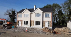
 Figure 1: front page of the ParexLahabra Agrément certificate showing a house in the ‘Ard na Mara’ estate of Malahide |
At this point the guidance seems to divide on two paths. The more onerous path closely reflects the new focus on thermal bridging in new-builds. Clause 2.1.3.2 refers to table D1 (8) of appendix D which lists thermal bridge (or Psi) values, and the tranche of ‘Acceptable Construction Details’ (ACD) (9) each of which is given a fixed Psi-value. Using these allows a good practice 'Y-factor' of 0.08 W/m2K, which is ahead of the minimum standard for new-builds of 0.15 W/m2K. At this level of performance minimization of thermal bridging goes beyond basic condensation control to playing a big role in reducing the overall heat loss of the building. See figure 1 of the introduction to the ACDs for further information. Even though the Psi-values listed represent good practice we see two problems with this clause:
A) The ACDs are for new-build, they have questionable relevance to many conditions that occur in refurbishment. For instance there is no ACD for a solid brick wall or a concrete eaves or the weights-box of a sliding sash window.
B) The Psi-values listed in table D1 become harder and harder to achieve as the U-value of the plane element increases (in both new-build and refurbs). Thus a Psi-value of 0.04 W/mK for a sill where the wall is 0.6 W/m2K is much easier to achieve than with 0.27 W/m2K. But anyone who uses the ACDs in designing building fabric to a super-insulated level (in other words 0.15 W/m2K) will get much poorer values than those listed in table D1. In fact those designers shouldn’t be allowed use the 0.08 Y-factor referred to in appendix D, as it bears little relation to the real value that would result!
 showing ‘thermal bridge-free’ details for refurbishment") Figure 4: diagram 2 from TGD L (2007) showing ‘thermal bridge-free’ details for refurbishment |
Effectively the current ACDs are only relevant to one level of thermal performance, and are only obliquely relevant to refurbishment at all.
If that is the first, let’s say higher path, the lower path is set-out in clauses 2.1.3.3 and diagram 2. In this author’s view these are in direct conflict with the clauses before them and are a clear hangover from the new-build standard of previous editions of TGD L. Diagram 2 in fact dates back to TGD L (1997) and is dreadfully out-of-date. Its ‘thermal bridge-free’ details are shot through with thermal bridges (see figure 5 below). In turn clause 2.1.3.3 refers vaguely to 15mm of 0.04 W/mK insulation as being ‘generally adequate.’
So should the sill be refurbished to a good performance-based standard of 0.04 W/mK (Psi-value) or a poor prescriptive-based standard of 15mm of mineral wool wrapped around its back? The weaker standard is about preventing the worst impacts of thermal bridging (condensation and mould) rather than avoiding excessive heat loss, but relates only to jambs, sills and lintels. It is clear in light of the current move towards low carbon housing that this standard is inadequate and incomplete. The more onerous standard, on the other hand, relates to all junctions. Presumably most builders will choose to follow the weaker standard where possible, but what about other junctions? It's clear there's a lot of room for confusion.
 with peach arrows added (see figure 4). The details on the right are meant to contrast with that on the left as having no thermal bridges, but they clearly do have.")
Figure 5: excerpts from diagram 2 from TGD L (2007) with peach arrows added (see figure 4). The details on the right are meant to contrast with that on the left as having no thermal bridges, but they clearly do have.
The result of all this is that it is genuinely hard to say what the minimum enforceable standard for thermal bridging in refurbishments is. It is reasonable to deduce that there may have been a rush in drafting the document or that an oversight occurred, but it is probably fair to say that the effect of thermal bridging in refurbishment has just not been considered that important on all sides of the construction industry until now. The economic slowdown and the HES scheme have certainly caused a shift in focus. Coherent guidance on minimum, enforceable standards for thermal bridging in refurbishment, as a clear step towards dwellings with ‘zero-carbon emissions’, would be a most valuable outcome of the review of TGD L (2007) that starts in September 2009.
The author's suggestion for this element of that review is twofold. Firstly, that the revised document could state clearly that all refurbishment should at least meet the same 0.15 Y-factor as new-build. Given that thermal bridging is about extra-over heat loss, this is not unreasonable but would bring considerable clarity. Secondly, that a new table of Psi-values be produced to sit alongside Table D1, for use in both refurbishment and new-build, that would show how each junction contributes to the overall 0.15 Y-factor.
A house in ‘Ard na Mara’
There is some irony in the fact that one of the houses this office has been commissioned to refurbish is in the same housing estate as the test house used for the ParexLahabra Agrément certificate, Ard na Mara in Malahide. Compare the front cover of the certificate (figure 1) with figure 6. This means we have virtually identical information and drawings for the house, can make an independent assessment of how to refurbish it with EWI and can then refer back to the certificate.


Figures 6, 7 & 8: front and side elevations and typical section through study house
The section shown in figure 8 is fascinating simply because it shows once again how accustomed we were as a people to living with little or no insulation. The only insulation this house had, when we surveyed it, were double glazed windows and the quilt insulation indicated in beige on the section. Both of these were installed decades after it was built in the late ‘50s.
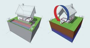
The house has hollow block walls to the two sides and rear, and a cavity wall to the front. That cavity is about 65mm wide and is uninsulated. There is a large cut-rafter roof and two large rooms and two bathrooms on the first floor. Our proposal is to fill the cavity to front (if it’s a suitable candidate), install EWI to the three sides, insulate the floor, and renovate and insulate the roof. The works to the roof are as per the energy-efficient upgrade of House A described in www.energyquarter.ie which involves changing from a ‘cold’ to a ‘warm’ roof build-up (10). There will also be a new condensing gas boiler and heating controls.
Assessing the NSAI Agrément certificate for ParexLahabra
Both NSAI Agrément and the British Board of Agrément (BBA) are national representatives of the ‘European Union of Agrément Institutes for Construction’ (UEAtc) and the European Organisation for Technical Approvals (EOTA) for their respective countries. The BBA frequently issues ETAs but NSAI Agrément has never done so. The recent changes referred to at the start of the article suggest that NSAI Agrément is a less than active member of EOTA.
NSAI Agrément staff state that their Agrément is worth the extra cost for a supplier that already holds an ETA because it assesses the product as installed here in Ireland. From this one can presume that an Irish Agrément cert, while not an installation manual, should still be more detailed and more specific to Irish conditions, including regulations, weather and building types, than an ETA. The assessment that this article is based on was an opportunity to examine that claim.

Figure 9: Excerpt from BR 262 showing UK exposure zones
Weather
The Agrément certificate makes no reference to weather conditions or whether the system can be used in every part of the country. TGD A has some wind speed maps but the only reference the certificate makes to TGD A is to do with strength, stability and ground movement. This is a lost opportunity as EWI, for all its advantages, is not necessarily suitable in every location. In contrast at least one UK technical approval requires that the EWI supplier carries out additional detailed calculations every time their product is to be used in very exposed conditions. The map that establishes these zones is excerpted above, with ‘very severe’ exposure areas coloured blue. It is taken from ‘BR 262 Thermal insulation - Avoiding the risks’, a document that is referred to in relation to condensation at the start of TGD L (clause 0.2.1) but deals with more traditional forms of construction than EWI.
The UK map aggregates wind with rainfall at a far greater level of detail than the maps in TGD A. If it were extended, a good portion of Ireland’s western seaboard would surely be coloured blue. Could NSAI Agrément commission such an extension to this map and refer to weather and exposure in any ETA or Agrément certs it issues?
Thermal performance & thermal bridging
The key quote in relation to thermal performance in the Agrément certificate is:
‘When designed and installed in accordance with this certificate, the system will satisfy the requirements of Part L of the Building Regulations 1997 to 2008. The design shall include for the elimination of cold bridging at window and door reveals, eaves, and at ground floor level.’
- Excerpt from Section 3.2, Design Data of the Agrément certificate
We are aware that NSAI Agrément may state that details shown in certificates are only indicative and that the focus is on weather-tightness, not construction or thermal performance. However, based on the requirement for Agrément certified EWI systems only being introduced by SEI under the HES scheme, some state agencies are clearly of the view that Agrément certificates are of greater value and more applicable in Ireland than ETAs. The argument being that NSAI Agrément assesses the system as installed, and because it states above that the system will satisfy all aspects of the Building Regulations and shall eliminate ‘cold bridging’ if the certificate is followed, suggests that the details given are intended to show far more than weather-tight seals.
An assumption has been made in this article that the construction details shown in the certificate relate to the house photographed on its cover. It would certainly be strange to omit a key detail of that renovation and show something else less relevant. We have therefore used the details literally. There is a sill detail, an eaves detail and two jamb details shown. The relevance of two jamb details is not explained. In our thermal bridge assessment we have used the jamb detail that agrees with the only sill shown.
While these details could be used to bring a refurbished wall up to 0.60 W/m2K, the minimum standard allowed in table 5 of TGD L (2007), it is highly unlikely this would be done, because (a) EWI is an expensive system and therefore tends to be used to obtain significant improvements and (b) the HES scheme grant is focused on achieving 0.27 W/m2K for walls or better. The thermal upgrades studied below are therefore all based on achieving 0.27 W/m2K for plane elements.
Assessing the major junctions
We carried out a thermal bridge assessment of the original house and three approaches to refurbishment. House 1 is the original house as surveyed. House 2 represents a literal interpretation of the Agrément cert’s details as per figure 10. House 2a is the same as House 2 in relation to eaves and footing but different in relation to ‘lintels, jambs and cills’ where it uses the 15mm of 0.04W/mK insulation from TGD L (2007) clause 2.1.3.3. House 3 features details developed in our office that have been assessed for thermal bridging and were selected for their suitability in this house.

Figure 10: four details from the NSAI Agrément certificate
The thermal bridges assessed in this study included the junctions around windows and doors, thresholds, the horizontal junctions with eaves and ground, the pitched junction at gables, and the two vertical junctions of hollow block walls at corners, and the other two junctions of the hollow block walls with the front cavity wall. Figure 16 shows these aggregated per version.
")
Figure 16: the breakdown of thermal bridging by each junction type (units W/K)
The first thing to note about the ψ-values is that the best (in other words lowest) values are House 1 (before works are done) and House 3. Despite refurbishment work the proportion of heat lost through these junctions (compared to the walls) in Houses 2 and 2a is higher than in the original house. Note however that doesn’t necessarily mean the actual heat loss (W/K) is higher. We shall assess this later.
The next thing to note is that the Agrément detail for the sill has an extremely poor ψ-value. It is 16 times worse than the TGD L appendix D value of 0.04 W/mK. House 2a in which we’ve inserted 15mm of insulation does better. The reverse is true at the jambs where the 15mm is not equal to the 40mm or so shown in the Agrément detail. In contrast both House 3 details show the important step of always moving the window forward. This goes hand-in-hand with removing the concrete sill and casting concrete in the resulting gap to create a smooth structural surface to fix to. A sill only 0.01 W/mK poorer than that listed in appendix D for a new-build sill is a good standard for refurbishment.
As 0.05 W/mK is allowed for a jamb in appendix D none of the jambs shown here performs too badly: this is very useful as the length of jamb thermal bridges is normally much larger than the length of sill thermal bridges, there being two jambs to every sill!
A huge difference is evident at the eaves. The Agrément drawing suggests new insulation being brought up to an existing soffit board (see figure 10). There is no reference made to removing fascia boards or to the height of the internal face of the wall. This is a significant omission. The result is a very long and wide thermal bridge for House 2 or 2a. The House 3 approach involves the fascia boards removed and stored, the insulation brought up to meet the new roof insulation overhead to ensure thermal continuity and the fascia replaced with a cut-down soffit board. The impact of the different design decisions is that House 2 or 2a has a thermal bridge 17 times higher than given in appendix D while House 3 meets it exactly.

Figure 13: two approaches for EWI given slab-on-ground floors
The study house has a concrete slab in the kitchen area and a suspended timber floor elsewhere. The Agrément certificate shows the insulation stopping at what we understand to be the existing ground level, termed ‘finish grade’ on its details. We wished to assess if stopping the insulation there or continuing the insulation 400mm below ground level made much of a difference for the two different floor build-ups. 75mm of insulation has been shown under the floor slab in Figure 13, and we show new insulation suspended between the joists in the case of Figure 14.
Appendix D allows a ground floor thermal bridge of 0.16 W/mK. In figure 13 House-2 or 2a are 40 per cent above this, while House 3 is 50 per cent less showing that EWI insulation should always be brought below ground level for solid floor slabs (where floor level and ground level are 150-200mm apart). The difference is less striking in the suspended floor case, probably because suspended timber floors tend to be higher above ground to allow ventilation in the first place. Bringing insulation below ground level is still well worth doing but other considerations could also play a part – it goes without saying that there is a cost in saw-cutting and removing paving around a house. Care also needs to be taken in relation to any buried cabling or gully traps: a competent builder who understands what one is trying to achieve is essential. Figures 15 and 16 should help this in graphically illustrating the consequent energy savings.
")
Figure 15: total heat loss associated with walls, including door, windows and thermal bridging (units W/K)
As per clause 2.1.3.1 of TGD L (2007) we carried out a study to see if any of the junctions in Houses 1, 2, 2a and 3 could suffer from surface condensation by establishing the temperature factor (fRsi) as per appendix D, TGD L (2007). The temperature factor should be higher than 0.75 to avoid risk of surface condensation and mould. Interestingly we found that the ground, eaves, gable and sill of House 1 were all at risk, and the corner junction of the side hollow block walls with the front cavity in particular (its value was 0.58). House 3 was at no risk, and House 2 was at marginal risk in relation to its sill which came in at 0.77.
Calculating the overall heat loss for each approach – the significance of thermal bridging
Figure 15 shows the overall heat loss of the house as studied in its three main forms: House 1 (the untouched house), House 2 (as per the Agrément certificate) and House 3 (as per this office’s details). The blue colours represent heat loss through plane elements and the red represents additional heat loss at junctions due to thermal bridging. The former is usually shown in W/m2K and the latter in W/mK which makes them hard to compare. To change this we brought everything to W/K. Therefore we no longer need to talk about the proportion of the heat loss via thermal bridging in one version compared to another: we can now see the actual heat loss in the same units.
Two points become immediately evident:
• There has been a large drop in the heat loss through the hollow block walls, as expected – 86.7 per cent. As doors and windows weren’t changed in this study, but rather moved forward to reduce the impact of thermal bridging, their plane element heat loss doesn’t diminish.
• However the details shown in the Agrément certificate, if applied literally, cause the heat loss (W/K) through junctions of the wall assembly to almost treble (rising from 16.0 - 46.4 W/K, see table 2). This is shocking. In contrast House 3 shows a reduction of 27.5 per cent in heat loss through junctions.

Table 2: Summary of outputs of heat loss calculations
In figure 16 we can look at the thermal bridging more closely. House 2a is only shown in part here because it is identical to House 2 excluding ‘lintels, jambs and cills’. Surprisingly the impact of using 15mm of insulation at those junctions ends up being comparable in impact to the Agrément details assessed. The sill of 2a is better but the jambs and lintel are much worse. Bundled together heat loss around windows goes from 4.5 W/K in House 1 to 7.7 W/K in House 2 down to 1.2 W/K in House 3.
The huge difference is at the eaves. The heat loss jumps from 4.5 W/K to 22.1 W/K in House 2 then down to 1.2 W/K in House 3 (see figure 12). Because we extrapolated that the fascias along the gables wouldn’t be removed if they weren’t removed elsewhere, the gables (in yellow) also show a marked increase in heat loss for House 2.

Figure 12: Two approaches for EWI at eaves
It is clear that guidance can and should be given on these kind of issues in an EWI Agrément cert or ETA. Simply adding a second eaves detail to show insulation continuing past the fascia soffit and a sentence or two emphasising (a) the importance of continuity of insulation and (b) taking account of internal room heights would make all concerned clear that there are choices to be made – choices which could have major ongoing costs savings and carbon emission reductions. Otherwise it would be better not to show any details at all.
Y-factor, cost to the homeowner and compliance
Having established the difference in energy loss for different approaches to insulating the same house’s walls to 0.27W/m2K, three questions emerge:
1) Is it possible to say what the ‘Y-factor’ (11) for the aggregated thermal bridges (Psi-values) of the house is?
2) What is the additional heating cost of House 2 compared to House 3 due to thermal bridging? And finally
3) Is House 2 compliant with the Building Regulations?
The Y-factor is a figure which one can multiply against the building’s exposed surface area which gathers together the impact of all thermal bridges. Though compensation of one junction by others is possible within that figure, it’s a useful comparator of the general extent of thermal bridging present. For instance, if one follows the details show in the ACDs document a Y-factor of 0.08 may be inputted in DEAP. Other structures, built to comply with the new-build standard in TGD L (2007) but not the ACDs, must use the 0.15 Y-factor, unless direct measuring or numerical modelling is used. We have used the latter approach for this study.
As we are concentrating on the (externally insulated hollowblock) wall assembly and its junction with the rest of the building we have information on most but not all junctions, so can’t calculate a Y-factor for the whole house. We can however assess the impact of what we do have: this is simply done. For a house of 200m2 a Y-factor of 0.15 W/m2K results in 30 W/K of aggregated heat loss through thermal bridges. Row C of table 2 above shows that the thermal bridging of the wall assembly of House 1 is 16.0 W/K, House 2 is 46.4 and House 3 is 11.6. This means that the Y-factors for the three versions of the study house (when the remaining thermal bridges are added in) are likely to be higher than 0.08 W/m2K for House 1, 0.23 for House 2 and 0.06 for House 3. This suggests that it is likely that House 3 could use the coveted 0.08 Y-factor in DEAP (after all calculations are concluded) but that House 2, using a literal interpretation of the NSAI Agrément details, would be more than 53 per cent worse than the poorer of the two new-build standards (0.15 W/m2K).
As per table 2 the difference in heat loss through House 2’s thermal bridges is 34.8 W/K compared to House 3. This is for 1oK of temperature difference: the actual temperature difference between inside and out will vary through the year. Looking at the DEAP file which had been prepared for the House 3 refurbishment project we took the ‘required mean internal temperature during heating hours’, 18.52oC, and the temperature difference for each month of the heating season. We then calculated that the additional space heating requirements imposed by the House 2 approach, over that of the House 3 approach, was 2,206 kWh or 11 kWh/m2 for this 200m2 house. Using the ‘Total Heating Cost Comparison Tool’ (12) on SEI’s website we established that, using a condensing gas boiler and assuming 7 per cent increases in annual heating costs over the next ten years (which Richard Douthwaite advised us some time ago was possible though conservative), this additional heating requirement would cost the householder e711 in year one and cumulatively over the decade would cost him/her e2,439. Money for old rope.
So can House 2 be compliant with the Building Regulations based on a literal interpretation of this NSAI Agrément certificate? Looking back at the clauses of TGD L (2007), as listed in table 1 above, it would appear that it cannot be. However, the clauses are so ambiguous it makes it difficult to say with certainty. The more onerous standard of clause 2.1.3.2 cannot be met using the information given in the certificate and the less onerous standard of 2.1.3.3 could only be met if 15mm of insulation is wrapped around the room face of the junctions, which is not shown in the certificate’s details or referred to in the text. The main guidance, given in clause 2.1.3.1, states that ‘reasonable care should be taken to ensure continuity of insulation and to limit local thermal bridging’. In the view of this author, given the lack of insulation continuity shown in the certificate, the resulting significant thermal bridges and additional heating cost, this document will not assist builders and designers in complying with the guidance of clause 2.1.3.1 or the basic law as stated in ‘L1’ (see figure 2).
")
Figure 2: extract from pg. 5 of Technical Guidance Document L (2007)
Please note this opinion does not reflect in any way on the quality of ParexLahabra external wall insulation. Nor does it reflect on the ParexLahabra technical team. The certificate states that they give support on a ‘project specific basis’. They may well give excellent support, carry-out detailed site and thermal bridge analysis, help ensure building regulations compliance and rely very lightly on this certificate.
Conclusion
Based on this research the author considers this certificate flawed and incomplete. It may indeed make the job of the ParexLahabra technical team more difficult in advising designers and builders to create regulation-compliant wall refurbishments. We urge that it be withdrawn and amended.
It is still not clear to the author, or to many others, why Agrément certificates with the current level of detail are supplanting a wide number of excellent ETAs in relation to EWI for use under the HES scheme. We want clever systems, more choice and good prices. Besides references to Irish regulatory standards and codes, Agrément certificates do not appear more detailed or ‘local’ than ETAs. If the case for local and installed value is to be convincingly made Agrément certificates need to be more useful to installers and more specific to Ireland by referencing a wealth of local information, such as the impact of severe weather conditions on the system assessed, and information and issues that will impact upon performance. It would be very useful if they could, for instance, allow easy calculation of Psi-values and provide equivalent details to the ACDs for that construction system.
The regulatory requirements for conserving fuel and energy in relation to thermal bridging in existing dwellings are currently inadequate, however a great opportunity exists in the upcoming review of Technical Guidance Document L to put this to rights. The marked shift to a refurbishment-focused building industry and the ambition in the HES scheme to raise the thermal standards for refurbishments to new-build levels make this all the more urgent.
In the context of climate change, resource depletion et cetera, Minister Gormley rightly wants to push the construction industry towards ‘zero carbon emissions associated with the operation and use of dwellings, at the earliest date practicable’ (13). For that to succeed all parties involved in construction in Ireland (government, professionals, builders and suppliers) need to pull together and focus on each of the steps that will get us to that goal. A key part must be integrated guidance, another must be wide access to good products. It will not be easy but working together we have a good chance of reducing the carbon emissions of our housing stock to zero, not by 2020 but perhaps by 2035, and creating a large number of jobs and a more sustainable society in the process.
1 This certificate can be downloaded at: http://www.nsai.ie/index.cfm/area/page/in
2 Don’t be confused! External wall insulation (EWI)is known as an external insulated façade system (EIFS) by NSAI Agrément and as external thermal insulation composite system (ETICS) by the European Organisation for Technical Approvals.
3 Bell, M. (2004) Energy efficiency in existing buildings: the role of building regulations, RICS COBRA conference, Centre for the Built Environment, Leeds Metropolitan University, UK.
4 See housing statistics at: http://www.environ.ie/en/Publications/ .
5 Information on the EU’s 20-20-20 policy may be downloaded at http://ec.europa.eu/energy/strategies/index_en.htm .
6 Thermal standards jumped 40 per cent above those of TGD L (2005) in TGD L (2007), which came into law on July 2008 and will jump a further +20 per cent in 2010.
7 Technical Guidance Document L (2007), Clause 0.1.3, pg. 7
8 Technical Guidance Document L (2007), Appendix D, Table D1, pg. 67
9 ‘Limiting Thermal Bridging and Air Infiltration - Acceptable Construction Details’ (published July 2008) is the Dept of Environment, Heritage and Local Government’s guide to help the construction industry in the identification, measurement and management of airtightness and thermal bridging in standard construction details. The full document can be downloaded from http://www.environ.ie/en/TGD
10 See upgrade roof details on http://www.energyquarter.ie/pages/house-a-upgrade/
11 Technical Guidance Document L (2007), AppendixD, Table D1, pg. 68 and Appendix 1, p. 35 of the ACDs.
12 This useful calculator can be found at: www.sei.ie/Publications/Statistics_Publications/Fuel_Cost_Comparison/
13 Technical Guidance Document L (2007), Clause 0.1.3, pg. 7
The Building Life Consultancy service of Joseph Little Architects is available to assist designers, material suppliers and systems manufacturers meet or exceed the thermal standards of the Building Regulations or the
Passivhaus Institut We can also simulate the hygrothermal performance of building envelopes for different locationsand exposures in Ireland using real weather data.
Contact This email address is being protected from spambots. You need JavaScript enabled to view it. for more information.
Read the full Breaking the mould series
- Articles
- home energy saving scheme
- Breaking the mould part III
- NSAI
- agrément
- thermal upgrade
- single leaf
- ParexLahabra
Related items
-
 BaseTherm liquid floor insulation gets Agrément cert
 -
 Kilsaran gets NSAI cert for EWI to steel frame
 -
 KORE gets NSAI cert for insulated foundation
 -
 Glavloc awarded Agrément certificate
 -
 Passive Sills get BBA cert
 -
 Keystone’s Hi-therm+ Lintel receives BBA cert
 -
 Passive Sills gets Agrément cert
 -
 Quinn Building Products launches free CPD on single leaf masonry
 -
 Heat pump grants - what you need to know
 -
 Passive House Systems gets first ever NSAI Agrement cert for solar PV
 -
 Amvic Ireland ICF gets updated Agrément cert
 -
 Codema launch energy saving kits in Dublin libraries